Sunday, 13 May 2018

Reading From SDRAM

Foreword

In the previous post we manage to pass pixel data from one clock domain to another and getting it displayed it on a VGA screen.

The above was a very nice practical test for me around all the theory surrounding cross clock domains. I must admit, I was quite overwhelmed with all the theory surrounding Cross Clock Domains on the Internet.

When overwhelmed with theory one must always attempt, if you can, to do a simple practical test for a reality check 😄

The next big goal is to attempt to read frames from SDRAM and display it on a VGA screen. This is quite a big chunk to perform at once, so we will try and break it down in small chunks.

In this post we will try and see if we can attempt to read from SDRAM to FPGA. We have already managed to write to SDRAM in a previous post, so the reading shouldn't be that hard.

However, the only part that concerns me with the reading is that our pixel clock clock is operating at speed very close to our AXI clock speed, so we must validate if our AXI system can keep up with with sufficient performance.

So, in this post I will also show a very primitive way for checking AXI-bus performance.

The Plan

Throughout this whole Blog-series I have been following the approach of divide and conquer.

This just makes life simpler when exploring new turf and should you encounter a bug you limit the scope you need to search in order to isolate the problem.

This is also the reason why we are only going to focus in this post in reading from SDRAM to FPGA.

But, in order to validate that we are reading data correctly from SDRAM, we need to be able to populate SDRAM with known data in the first place.

So, what is an easy way to populate SDRAM with known data? The Xilinx SDK come to our rescue here.

The XCST console integrated within the Xilinx SDK actually allows you to write a binary file that is present on your desktop machine directly to SDRAM on the Zybo Board at an address you specify.

Since our main goal is to develop a C64 on FPGA I am going to use the XSCT console to write a copy of the BASIC ROM from the C64 to the SDRAM of the Zybo board.

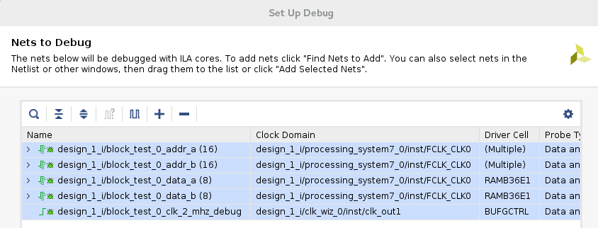
We are then going to attempt to read this binary back from SDRAM to our FPGA by means of our developed design and inspect the data that comes back by means of an Integrated Logic Analyser.

I have covered the use of an Integrated Logic Analyser in a previous post.

To make things more interesting we will take the data received from SDRAM, which is in 32-bit word form, and output it to a 8-bit port in a byte by byte fashion, Reliving the 8-bit area!

Reusing old code

To make our development a bit faster, we will be reusing our code developed in a previous post where we managed to write to SDRAM. With some tinkering we can make it read from SDRAM.

Let us refresh our minds again on how this code worked.

The whole design revolves around the IP provided by Xilinx called the LogiCore AXI Master Burst

The relevent IP Core I have just described is indicated by the block AXI Master Burst.

This block connects to the outside world via AXI. Our user logic will connect to this block via the IPIC protocol which is somewhat simpler than the AXI protocol.

Now, we need to wrap the AXI Master Block within an IP within Vivado so we can add it as a block within our Block Design.

We will then wire up the rest  of our design to this Block.

In the post where have implemented the functionaslity for writing to SDRAM, we encapsulated the user related logic within a module called burst_block which had the following signature:

module burst_block(
  input wire clk,
  input wire reset,
  input wire write,
  input wire [31:0] write_data, 
  output wire [31:0] ip2bus_mst_addr,
  output wire [11:0] ip2bus_mst_length,
  output wire [31:0] ip2bus_mstwr_d,
  output wire [4:0] ip2bus_inputs,
  input wire [5:0] ip2bus_otputs

    );

All the port which names starts with ip2,  forms part of the IPIC which is connected to the AXI MASTER Block.

During the course of this post we will rework both the module burst block and our AXI IP to cater for SDRAM reading.

I want to stress though that I will however not change these two components to provide dual functionality, but rather make copies and change the copies to provide the read functionality.

Thus, in the end we will have a AXI IP and burst_block providing the AXI write functionality and we will have another AXI IP and burst_block-set providing the read functionality.

The new AXI IP Block

Let us start by creating a new AXI IP Block for reading.

As mentioned in a previous post, you will start off this process by clicking on the Tools menu, selecting Create and Package new IP, and selecting Create AXI Peripheral on the second wizard page.

I am not going to bore you with the whole process again, but let us have a look at how the complete AXI Block will look like in the block design:


This block almost looks the same as the one we have develop for writing to SDRAM.

The real major difference is that we don't have a data input port, but a data output port.

Another difference is the assignment of m00_axi_aruser[0] and m00_axi_awuser[0]. These assignments will change as follows:

    assign m00_axi_aruser[0] = 1'b1;
    assign m00_axi_awuser[0] = 1'b0;


In our Write Axi block from a previous post we swapped around the zero and one values. Because this block is a read block, we are interested in Coherent reads rather than writes.

Just to refresh our minds again, we are making use of the ACP AXI port on the processing subsystem, in which we see memory in exactly the same way as the two ARM cores see memory. For that reason we need to worry about coherency. Here is a quite quote from the Technical Reference Manual for the Zynq, regarding above mentioned ports:

ACP coherent read requests: An ACP read request is coherent when ARUSER[0] = 1 and ARCACHE[1] = 1 alongside ARVALID. In this case, the SCU enforces coherency. When the data is present in one of the Cortex-A9 processors, the data is read directly from the relevant processor and returned to the ACP port. When the data is not present in any of the Cortex-A9 processors, the read request is issued on one of the SCU AXI master ports, along with all its AXI parameters, with the exception of the locked attribute.

ACP coherent write requests: An ACP write request is coherent when AWUSER[0] = 1 and AWCACHE[1] =1 alongside AWVALID. In this case, the SCU enforces coherency. When the data is present in one of the Cortex-A9 processors, the data is first cleaned and invalidated from the relevant CPU. When the data is not present in any of the Cortex-A9 processors, or when it has been cleaned and invalidated, the write request is issued on one of the SCU AXI master ports, along with all corresponding AXI parameters with the exception of the locked attribute.
Why do we need to look at memory in the same way as a CPU core? The answer is that because we will be using XSCT console to write test data to SDRAM for reading back later by our user logic.

The XSCT console, however, always operates within the context of a CPU core. So reads/writes that we do from this console will always be from a L1 or a L2 cache. So, if we make use a AXI master port accessing the DDR RAM directly, like HP AXI or GP AXI, we might not read the data back that we wrote via the XSCT console.

Changes to block_burst

Let us create a new block_burst for doing reading. The definition of this new will looks as follow:

module burst_read_block(
  input wire clk,
  input wire reset,
  input wire restart,
  output wire [31:0] ip2bus_mst_addr,
  output reg [11:0] ip2bus_mst_length,
  input wire [31:0] ip2bus_mstrd_d,
  output wire [31:0] axi_d_out,
  output wire [4:0] ip2bus_inputs,
  input wire [5:0] ip2bus_otputs,
  output wire empty,
  input wire read
    );


A major change compared to the previous AXI write module is that our module will now be receiving data from the AXI port and the rest of our design will now read data from this block.

Our FIFO buffer contained within this module will also have its read and write ports swapped around a bit:

fifo #(
  .DATA_WIDTH(32),
  .ADDRESS_WIDTH(5)
)

   data_buf (
            .clk(clk), 
            .reset(!reset | restart),
            .read(read),
            .write(!master_read_src_rdy & bytes_to_receive > 0),
            
            .write_data(/*write_data*/ip2bus_mstrd_d),
            .empty(empty), 
            .full(),            
            .read_data(axi_d_out)
        );


The read port will now be driven user logic instead of the AXI port.

However, the write port will now be controlled by the AXI port via master_read_src_rdy. It should be noted that source and destination is different within a AXI read context. Within a AXI read context, the source is SDRAM and the destination is our user logic.

Apart from the master_read_src_rdy signal, bytes_to_received is also used to indicate that a write should happen to the FIFO buffer.

bytes_to_received keeps track of how many bytes we have still expect from the AXI port that we asked it to send:

always @(posedge clk)
 if (state == START)
 
   bytes_to_receive <= BURST_THRES;
 else if ((state > START) & !master_read_src_rdy & bytes_to_receive != 0) 
   bytes_to_receive <= bytes_to_receive - 1;


We initialise this register when our state machine is in the START status.

Our state machine uses the same states as with our AXI write mechanism, with some minor changes to the conditions for transitioning to other states, but more on this in a moment.

You might have noticed we are referencing a port called restart. I am using this port to cater for the scenario where we are constantly reading frames from SDRAM.

When we have finished reading a frame from SDRAM, we would like to reset the memory pointer to the beginning of the frame.

The first place you might have seen we use this port is on the reset port of the data_buf. So, on a restart we will empty the FIFO. The other places we need to make use of this signal within our module is shown below:

...
always @(posedge clk)
if (!reset | restart)
  count_in_buf <= 0;
else if (!read & write)
  count_in_buf <= count_in_buf + 1;
else if (read & !write)    
  count_in_buf <= count_in_buf - 1;
...
always @(negedge clk)
if (!reset | (restart))
begin
  axi_start_address <= 32'h200000;
  axi_data_inc <= 0;
end
else if (state == INIT_CMD)
begin
  axi_start_address <= axi_start_address + axi_data_inc;
  axi_data_inc <= {BURST_THRES,2'b0};
end    
...

The restart signal also needs to be used by state machine, which I haven't shown above, since it nees special mention.

In our state machine we cannot blindly reset the state to IDLE. We first need to wait for the AXI port to deliver it last batch of data:

always @(posedge clk)
if (!reset | (restart & bytes_to_receive == 0 & state == 0))  
  state <= 0;
else
  case( state )
  //cater for scenario of flush
    IDLE: if (count_in_buf < BURST_THRES) 
            state <= INIT_CMD;
    INIT_CMD: state <= START;             
    START: if (cmd_ack)
             state <= ACT;
    ACT: if (!master_read_src_rdy)
             state <= TRANSMITTING;
    TRANSMITTING: if (!master_read_src_rdy & bytes_to_receive == 1)
                    state <= IDLE;    
  
  endcase


Finally, let us quickly cover the assignments to some crucial ports:

assign master_read_src_rdy = ip2bus_otputs[3];
assign cmd_ack = ip2bus_otputs[0];
assign ip2bus_inputs[0] = mstread_req;
assign ip2bus_inputs[1] = mst_type; 
assign ip2bus_mst_addr = axi_start_address;
assign ip2bus_inputs[2] = master_read_dst_rdy;


Gluing everything together

With our new AXI IP and burst_block_read module developed, it is time we give it a test run.

As mentioned earlier, our test will be to write the BASIC ROM to SDRAM via the XSCT console and then see if our FPGA reads back the same information.

To do this test, we need to develop an extra Verilog module for gluing everything together. We will call this module axi_restart_test, and here is the complete code for this module:

module axi_restart_test(
  input wire clk,
  input wire reset,
  //input wire write,
  //input wire [31:0] write_data, 
  //output src ready
  //-----------------------------------------
  output wire [31:0] ip2bus_mst_addr,
  output wire [11:0] ip2bus_mst_length,
  input wire [31:0] ip2bus_mstrd_d,
  output wire [7:0] byte_out,
  output wire trigger_restart,
  output wire [4:0] ip2bus_inputs,
  input wire [5:0] ip2bus_otputs
    );
    
reg [31:0] byte_shift_reg;    
reg [1:0] byte_num = 0;
reg [9:0] bytes_to_send = 1023;
reg [1:0] state = 0;
reg [6:0] restart_counter = 63;
wire [31:0] data_buf_out;
wire empty;

assign trigger_restart = state == 2;  
    
burst_read_block my_read_block(
          .clk(clk),
          .reset(reset),
          
          .restart(trigger_restart),
           
          .count_in_buf(),
          
          
          .ip2bus_mst_addr(ip2bus_mst_addr),
          .ip2bus_mst_length(ip2bus_mst_length),
          .ip2bus_mstrd_d(ip2bus_mstrd_d),
          .ip2bus_inputs(ip2bus_inputs),
          .ip2bus_otputs(ip2bus_otputs),
          .axi_d_out(data_buf_out),
          .empty(empty),
          .read(!empty & byte_num == 0)
            );

assign byte_out = byte_shift_reg[31:24];

always @(posedge clk)
  case (state)
    2'b0 : state <= 1;
    2'b1 : state <= bytes_to_send == 0 ? 2 : 1;
    2'b10 : state <= restart_counter == 0 ? 0 : 2;    
  endcase
  
always @(posedge clk)
  restart_counter <= state == 2 ? restart_counter - 1 : 63; 
    
always @(posedge clk)
if (byte_num == 0 & !empty)
  byte_shift_reg <= data_buf_out;
else
  byte_shift_reg <= {byte_shift_reg[23:0], 8'b0};
  
always @(posedge clk)
if (state == 0)
  bytes_to_send <= 1023;
else if (state == 1 & !empty)
  bytes_to_send <= bytes_to_send - 1;
  
always @(posedge clk)    
  byte_num <= trigger_restart & empty ? 0 : byte_num + 1;
    
endmodule


This module takes the words received from the burst_read_block and it returns it byte for byte over the output port byte_out.

It also continuously outputs the first 1024 bytes of BASIC ROM which is retrieved from SDRAM.

With these modules developed, we can add them to our block design and wire everything up, which results in the following:

You can see on the image that I have also added an Integrated Logic Analyser on the right hand side. I have attached the following probes to the Integrated Logic Analyser:


  • ip2bus_mst_addr (32 bits)
  • ip2bus_mstrd_d (32 bits)
  • byte_out (8 bits)
  • trigger restart (1 bit)
  • ip2bus_inputs (5 bits)
  • ip2bus_outputs (6 bits)

Test Results

Let us have a look at the Test Results.

Probably the easiest way is just to view the captured waveforms in the Waveform window.

We have, however, also the option to view the captured data as a csv file, which we will use in this post.

To export the captured data as a csv file, you need to ensure that you have the tcl console open of the hardware manager. You then issue the following command within the Tcl console:

write_hw_ila_data my_hw_ila_data_file.zip [upload_hw_ila_data hw_ila_1]

You need to specify the full path for the resulting zip file. Also, hw_ila_1 is the name of your wave capture window.

When you open up the created zip, you will see a number files, of which one of them will be a csv file. In our case the csv file will like the following:


The fields are listed as below:

  • Sample in Buffer
  • Sample in Window
  • TRIGGER
  • design_1_i/axi_restart_test_0_byte_out[7:0]
  • u_ila_0_axi_restart_test_0_ip2bus_mst_addr_1[0:0]
  • u_ila_0_axi_restart_test_0_ip2bus_mst_addr_2[0:0]
  • design_1_i/axi_restart_test_0_ip2bus_mst_addr_1[5:2]
  • u_ila_0_axi_restart_test_0_ip2bus_mst_addr_3[31:6]
  • design_1_i/myip_burst_read_test_0_bus2ip_mstrd_d[31:0]
  • design_1_i/myip_burst_read_test_0_ip2bus_otputs[4:0]
  • u_ila_0_myip_burst_read_test_0_ip2bus_otputs[5:5]
  • design_1_i/axi_restart_test_0_ip2bus_inputs[2:0]
  • u_ila_0_axi_restart_test_0_ip2bus_mst_addr_4[0:0]
  • u_ila_0_axi_restart_test_0_ip2bus_mst_addr[0:0]
  • design_1_i/axi_restart_test_0_trigger_restart_1
You will see that some fields, like ip2bus_mst_addr, is broken down into two fields for some reason.

Now, let us see if we can analyse the data!

A good place to start is after a restart pulse, which will bring us to the beginning of the Basic ROM data. Let us have a look at a snippet after a restart pulse:

798,798,0,00,0,0,0,0008000,ca59c65b,08,0,4,0,0,1
799,799,0,00,0,0,0,0008000,ca59c65b,08,0,4,0,0,1
800,800,0,00,0,0,0,0008000,ca59c65b,08,0,4,0,0,1
801,801,0,00,0,0,0,0008000,ca59c65b,08,0,4,0,0,1
802,802,0,00,0,0,0,0008000,ca59c65b,08,0,4,0,0,1
803,803,0,00,0,0,0,0008000,ca59c65b,08,0,4,0,0,0
804,804,0,00,0,0,0,0008000,ca59c65b,08,0,4,0,0,0
805,805,0,00,0,0,0,0008000,ca59c65b,08,0,3,0,0,0
806,806,0,00,0,0,0,0008000,ca59c65b,09,0,3,0,0,0
807,807,0,00,0,0,0,0008000,ca59c65b,08,0,0,0,0,0
808,808,0,00,0,0,0,0008000,ca59c65b,08,0,0,0,0,0


I have highlighted in Bold Black the end of the restart pulse. I have indicated changes to other signals in red.

Let us see if we can puzzle out what the signal changes in red represent. First, let us have a look at the signal which change from a 4 to a 3.

From our column names we see that this column represents ip2bus_inputs. Let us quickly recap on the meaning of the different bits for this signal:

  • Bit 2: master_read_dst_rdy
  • Bit 1: mst_type
  • Bit 0: mstread_req
So, we can see that in transitioning from 4 to 3, we are signaling that we are ready to receive data and we issue a read request.

Let us now see if we can figure out the signal that changes from an 8 to a 9. This time we see that this signal represents ip2bus_otputs. The meaning of these signals are as follows:

  • Bit 0: bus2ip_mst_cmdack 
  • Bit 1: bus2ip_mst_cmplt
  • Bit 2: bus2ip_mst_error
  • Bit 3: bus2ip_mstrd_src_rdy_n     
  • Bit 4: md_error
So we see that Bit 0 transitions to 1 indicating the the AXI subsystem has indeed accepted our command!

What is funny, though, is that the two entries following the transition indicates that source ready signal is not asserted straightaway! This means that we don't have data available yet from our AXI system that we can read.

We only get data about 37 clock cycles later:

940,940,0,bc,0,0,e,0008001,f0c83aa4,08,0,0,0,0,0
941,941,0,58,0,0,e,0008001,f0c83aa4,08,0,0,0,0,0
942,942,0,bc,0,0,e,0008001,f0c83aa4,08,0,0,0,0,0
943,943,0,cc,0,0,e,0008001,f0c83aa4,08,0,0,0,0,0
944,944,0,b3,0,0,e,0008001,f0c83aa4,08,0,0,0,0,0
945,945,0,7d,0,0,e,0008001,f0c83aa4,08,0,0,0,0,0
946,946,0,03,0,0,e,0008001,f0c83aa4,08,0,0,0,0,0
947,947,0,10,0,0,e,0008001,f0c83aa4,08,0,0,0,0,0
948,948,0,bf,0,0,e,0008001,f0c83aa4,08,0,0,0,0,0
949,949,0,71,0,0,e,0008001,f0c83aa4,08,0,0,0,0,0
950,950,0,b3,0,0,e,0008001,f0c83aa4,08,0,0,0,0,0
951,951,0,9e,0,0,e,0008001,f0c83aa4,08,0,0,0,0,0
952,952,0,b9,0,0,e,0008001,f0c83aa4,08,0,0,0,0,0
953,953,0,ea,0,0,e,0008001,f0c83aa4,08,0,0,0,0,0
954,954,0,e0,0,0,e,0008001,f0c83aa4,08,0,0,0,0,0
955,955,0,97,0,0,e,0008001,f0c83aa4,08,0,0,0,0,0
956,956,0,e2,0,0,e,0008001,f0c83aa4,08,0,0,0,0,0
957,957,0,64,0,0,e,0008001,f0c83aa4,08,0,0,0,0,0
958,958,0,bf,0,0,e,0008001,f0c83aa4,08,0,0,0,0,0
959,959,0,ed,0,0,e,0008001,f0c83aa4,08,0,0,0,0,0
960,960,0,e2,0,0,e,0008001,f0c83aa4,08,0,0,0,0,0
961,961,0,b4,0,0,e,0008001,f0c83aa4,08,0,0,0,0,0
962,962,0,e2,0,0,e,0008001,f0c83aa4,08,0,0,0,0,0
963,963,0,6b,0,0,e,0008001,f0c83aa4,08,0,0,0,0,0
964,964,0,b8,0,0,e,0008001,f0c83aa4,08,0,0,0,0,0
965,965,0,0d,0,0,e,0008001,f0c83aa4,08,0,0,0,0,0
966,966,0,e3,0,0,e,0008001,f0c83aa4,08,0,0,0,0,0
967,967,0,0e,0,0,e,0008001,f0c83aa4,08,0,0,0,0,0
968,968,0,b4,0,0,e,0008001,f0c83aa4,08,0,0,0,0,0
969,969,0,65,0,0,e,0008001,f0c83aa4,08,0,0,0,0,0
970,970,0,b7,0,0,e,0008001,f0c83aa4,08,0,0,0,0,0
971,971,0,7c,0,0,e,0008001,f0c83aa4,08,0,0,0,0,0
972,972,0,b7,0,0,e,0008001,f0c83aa4,08,0,0,0,0,0
973,973,0,8b,0,0,e,0008001,f0c83aa4,08,0,0,0,0,0
974,974,0,b7,0,0,e,0008001,f0c83aa4,08,0,0,0,0,0
975,975,0,ad,0,0,e,0008001,f0c83aa4,08,0,0,0,0,0
976,976,0,00,0,0,e,0008001,b700b6ec,00,0,0,0,0,0
977,977,0,00,0,0,e,0008001,b737b72c,00,0,0,0,0,0


I had a look at a couple of subsequent read requests and all of them have this delay of more less 37 clock cycles.

So, we can conlcude that for each AXI read request, there is a 37 clock cycle latency.

Now, let us have a look at the actual data that comes through:

840,840,0,00,0,0,0,0008000,ca59c65b,08,0,0,0,0,0
841,841,0,00,0,0,0,0008000,ca59c65b,08,0,0,0,0,0
842,842,0,00,0,0,0,0008000,ca59c65b,08,0,0,0,0,0
843,843,0,00,0,0,0,0008000,e37be394,00,0,0,0,0,0
844,844,0,00,0,0,0,0008000,424d4243,00,0,0,0,0,0
845,845,0,00,0,0,0,0008000,43495341,00,0,0,0,0,0
846,846,0,00,0,0,0,0008000,a741a830,00,0,0,0,0,0
847,847,0,00,0,0,0,0008000,a8f7ad1d,00,0,0,0,0,0


This looks more or less like the data at the beginning of a C64 BASIC ROM, with the byte order reversed, though.

Let us now see if we can pinpoint the place where this 4 byte words gets output as a stream of bytes. This happens a couple of clock cycles after we start receiving data:

840,840,0,00,0,0,0,0008000,ca59c65b,08,0,0,0,0,0
841,841,0,00,0,0,0,0008000,ca59c65b,08,0,0,0,0,0
842,842,0,00,0,0,0,0008000,ca59c65b,08,0,0,0,0,0
843,843,0,00,0,0,0,0008000,e37be394,00,0,0,0,0,0
844,844,0,00,0,0,0,0008000,424d4243,00,0,0,0,0,0
845,845,0,00,0,0,0,0008000,43495341,00,0,0,0,0,0
846,846,0,00,0,0,0,0008000,a741a830,00,0,0,0,0,0
847,847,0,00,0,0,0,0008000,a8f7ad1d,00,0,0,0,0,0
848,848,0,e3,0,0,0,0008000,abbeaba4,00,0,0,0,0,0
849,849,0,7b,0,0,0,0008000,ac05b080,00,0,0,0,0,0
850,850,0,e3,0,0,0,0008000,a89fa9a4,00,0,0,0,0,0
851,851,0,94,0,0,0,0008000,b5489809,08,0,0,0,0,0
852,852,0,42,0,0,0,0008000,b5489809,08,0,0,0,0,0
853,853,0,4d,0,0,0,0008000,b5489809,08,0,0,0,0,0


The byte values looks more or less ok, except that just after the 64th byte we are presented with 8 zero byte values, which is not correct if you compare with the actual BASIC ROM data.

Some closer investigation yielded that this was caused by our AXI bus not been able to provide the data fast enough. To get an idea of the problem, I have created the following table:

000008000e37be394000
000008000424d4243001
00000800043495341002
000008000a741a830003
000008000a8f7ad1d004
0e30008000abbeaba4005
17b0008000ac05b080006
2e30008000a89fa9a4007
3940008000b548980908
4420008000b548980908
54d0008000b548980908
6420008000b548980908
7430008000a927a870008
8430008000a882a81c009
9490008000a93aa8d10010
10530008000a94aa82e0011
11410008000e167b82c0012
12a70008000e164e1550013
13410008000b823b3b20014
14a8000800001b033c508
153000f800001b033c508
16a800f800001b033c50a
17f700f800001b033c508
18ad00f800001b033c509
191d00f800001b033c508
20ab00f800001b033c508
21be00f800001b033c508
22ab00f800001b033c508
23a400f800001b033c508
24ac00f800001b033c508
250500f800001b033c508
26b000f800001b033c508
278000f800001b033c508
28a800f800001b033c508
299f00f800001b033c508
30a900f800001b033c508
31a400f800001b033c508
32a900f800001b033c508
332700f800001b033c508
34a800f800001b033c508
357000f800001b033c508
36a800f800001b033c508
378200f800001b033c508
38a800f800001b033c508
391c00f800001b033c508
40a900f800001b033c508
413a00f800001b033c508
42a800f800001b033c508
43d100f800001b033c508
44a900f800001b033c508
454a00f800001b033c508
46a800f800001b033c508
472e00f800001b033c508
48e100f800001b033c508
496700f800001b033c508
50b800f800001b033c508
512c00f800001b033c508
52e100f800001b033c508
536400f800001b033c508
54e100f800001b033c508
555500f8000aa9faa7f0015
56b800f80006c10a26008
572300f80006c10a26008
58b300f80006c10a26008
59b200f80006c10a26008
60aa00f80006c10a26008
619f00f80006c10a26008
62aa00f80006c10a26008
637f00f80006c10a26008
0000f80006c10a26008
0000f80006c10a26008
0000f80006c10a26008
0000f80006c10a26008
0000f8000a69ba8560016
0000f8000aa85a65d0017
0000f8000e1bde1290018
0000f8000ab7ae1c60019

This is basically a snippet of the CSV file converted into an HTML table.

I have also added an extra column on the left hand site and a column on the right hand side.

The column on the left hand site indicates when our byte output stream starts, and increment the count after each byte output. For byte count 64 and up the count cell is blank and indicates invalid data.

The extra column on the righthand site counts each time we receive a four-byte word from the AXI bus.

You can see that received word number 15 is the last word of data that arrives "in-time"and gets displayed during byte number 60, 61, 62 and 63.

Received word 16, however, only arrives some 5 clock cycles after byte value number 63 was outputted. So, we have a small buffer underflow issue here 😞

We can avoid this buffer underflow situation by tweaking the size of our FIFO receive buffer. The size of the buffer should be made just over twice the BURST_THRES paramater.

Which value of BURST_THRES should we choose? BURST_THRES should be set so that we trigger the next AXI read transaction with enough elements in our FIFO buffer to survive the latency of more or less 36 clock cycles.

So, to cater for a possible worst case scenario, we can probably choose a BURST_THRES of 50. So a typical FIFO buffer size for this scenario would 102 elements.

Just a final note on analysing the data in the CSV file.

Another kind of odd behaviour you might realise from the HTML table above is that once we start receiving the data words from the AXI subsystem, we receive it continuously from Word 0 to Word 7. However, after Word 7 there is a delay of four clock cycles before we receive data again.

You get this kind of behaviour for the other AXI read transactions as well, but for the majority of cases it is not only 4 delay cycles, but 6, 7 or 8 delay cycles!

Considering that we are requesting 16 data words at a time, these delay clock cycles eats more or less 50% of the available bandwidth!

Investigating the loss of Bandwidth

Let us see if we can figure out why our bandwidth is so low.

After some reading I found a clue.

The ACP-AXI port we are using is 64-bit wide on the Processing system side. Our AXI IP block, however, has a 32-bit wide data port instead of a 64-bit one.

I suspect that this 32-bit wide data port is the cause for our bandwidth issue.

The obvious check then be to extend the databus of our existing AXI IP also to 64-bit.

However, quickly looking at Vivado it doesn't seem so obvious to extend the databus width of a AXI created peripheral to 64 bits. There is an option to specify databus width from the dropdown, but in the drop-down, suprise-suprise, there is only a 32-bit option!

I am sure with some tweaking one could make a 64-bit option appear, but for now I want something simple to test my theory on whether the mismatch of port width is the cause for the bandwidth issue.

Another option would be to use an AXI port on the Processing subsystem that is also 32-bits wide. At least then we test if matching ports also result in the same amount of lost clock cycles.  

There is indeed an AXI port on the Processing subsystem that is 32-bits in width: The General Purpose (GP) AXI port.

To be honest, I have have been avoiding AXI-GP ports up to this point in time for the simple reason that it is not guaranteed that the FPGA will see test data we wrote via the XSCT console on an AXI-GP port. SO, let us see if we can move the bar higher and see if we can make the FPGA read data on the AXI-GP port written by the XSCT console.

To do this, let us have a look again at the question: Why can't we guarantee that memory writes via the XSCT console will be read back via the FPGA on the AXI-GP port?

The answer to this question is that memory writes via the XSCT console doesn't get written directly to DDR memory, but rather to the L1 cache associated with the ARM Core our XSCT console is attached to.

So, is there a way to flush the contents of the L1 cache to DDR memory? To answer this question, we need to look a bit in the ZYNQ Technical Reference manual on how the whole L1-Cache mechanism works.

The L1-Cache contains a number of Cache lines. When a request is made from Main Memory, the contents is read from DDR memory and then stored within a Cache Line. All subsequent requests to the same memory location is retrieved from the relevant Cache line within the L1-Cache.

With writes to main memory the relevant contents is first read from Main memory and stored within a cache line. The contents to be written is then applied to the relevant cache line, and the whole cache line is marked as dirty.

If we just left it there, we will just have a Cache line entry marked as dirty, which will never be written to Main Memory.

However, things start to change when we keep writing data up to a point when we have no free Cache Line entries left. In this scenario the L1 Cache Manager will choose a Cache Line entry to evacuate to accommodate the new write. The Cache Line entry chosen will usually be a Least Recently Read/Wite one.

If the chosen Cache Line is marked as dirty, the existing contents first gets written to main memory.

So, to ensure that our writes from XSCT console gets written to Main Memory we need to write a file that is bigger than the size of the L1 Cache.

The L1 Data Cache is 32KB, while the BASIC ROM we used previously for testing is 8KB in size. So we need to create new file by contenting the BASIC ROM a number of times till the resulting file is bigger than 32KB.

On the Bash Terminal in Linux this concatenated file can be produced with the following:

cat basic.bin basic.bin basic.bin basic.bin basic.bin basic.bin > big.bin

The file big.bin will then be the file you use to write to memory via the XSCT console.

Changing the Design to use an AXI-GP port

Let us change the design to make use of an AXI-GP port.

We this by double clicking on the Processing Sub System Block within the Block Design.

On the Page Navigator Panel on the Left select PS-PL Configuration and make the following selections:


We Unselect the ACP Salve Interface so that only one AXI Slave port is present on the Zynq Processing block.

Finally you need to wire everything up again.

Test Results with the AXI-GP port

This time around the results look a lot better. You obviously still have your about 37 clock latency for every AXI read transaction, but once the data starts coming in, it comes in without any intermittent delay clock cycles. With some read transactions you might see one or two intermittent delay clock cycle during the receiving of data, but that is about it:

.
.
.
1096,1096,0,00,ca59c65b,0,0,0,0,0,0,0008000,08,0,0
1097,1097,0,00,ca59c65b,0,0,0,0,0,0,0008000,08,0,0
1098,1098,0,00,e37be394,0,0,0,0,0,0,0008000,00,0,0
1099,1099,0,00,424d4243,0,0,0,0,0,0,0008000,00,0,0
1100,1100,0,00,43495341,0,0,0,0,0,0,0008000,00,0,0
1101,1101,0,00,a741a830,0,0,0,0,0,0,0008000,00,0,0
1102,1102,0,00,a8f7ad1d,0,0,0,0,0,0,0008000,00,0,0
1103,1103,0,e3,abbeaba4,0,0,0,0,0,0,0008000,00,0,0
1104,1104,0,7b,ac05b080,0,0,0,0,0,0,0008000,00,0,0
1105,1105,0,e3,a89fa9a4,0,0,0,0,0,0,0008000,00,0,0
1106,1106,0,94,a927a870,0,0,0,0,0,0,0008000,00,0,0
1107,1107,0,42,a882a81c,0,0,0,0,0,0,0008000,00,0,0
1108,1108,0,4d,a93aa8d1,0,0,0,0,0,0,0008000,00,0,0
1109,1109,0,42,a94aa82e,0,0,0,0,0,0,0008000,00,0,0
1110,1110,0,43,e167b82c,0,0,0,0,0,0,0008000,00,0,0
1111,1111,0,43,e164e155,0,0,0,0,0,0,0008000,00,0,0
1112,1112,0,49,b823b3b2,0,0,0,0,0,0,0008000,00,0,0
1113,1113,0,53,01b033c5,4,0,0,0,0,0,0008000,08,0,0
1114,1114,0,41,01b033c5,4,0,0,0,0,f,0008000,08,0,0
.
.
.
1153,1153,0,b8,01b033c5,0,0,0,0,0,f,0008000,08,0,0
1154,1154,0,2c,01b033c5,0,0,0,0,0,f,0008000,08,0,0
1155,1155,0,e1,aa9faa7f,0,0,0,0,0,f,0008000,00,0,0
1156,1156,0,64,6c10a260,0,0,0,0,0,f,0008000,08,0,0
1157,1157,0,e1,6c10a260,0,0,0,0,0,f,0008000,08,0,0
1158,1158,0,55,a69ba856,0,0,0,0,0,f,0008000,00,0,0
1159,1159,0,b8,aa85a65d,0,0,0,0,0,f,0008000,00,0,0
1160,1160,0,23,e1bde129,0,0,0,0,0,f,0008000,00,0,0
1161,1161,0,b3,ab7ae1c6,0,0,0,0,0,f,0008000,00,0,0
1162,1162,0,b2,bc39a641,0,0,0,0,0,f,0008000,00,0,0
1163,1163,0,aa,bc58bccc,0,0,0,0,0,f,0008000,00,0,0
1164,1164,0,9f,b37d0310,0,0,0,0,0,f,0008000,00,0,0
1165,1165,0,aa,bf71b39e,0,0,0,0,0,f,0008000,00,0,0
1166,1166,0,7f,b9eae097,0,0,0,0,0,f,0008000,00,0,0
1167,1167,0,a6,e264bfed,0,0,0,0,0,f,0008000,00,0,0
1168,1168,0,9b,e2b4e26b,0,0,0,0,0,f,0008000,00,0,0
1169,1169,0,a8,b80de30e,0,0,0,0,0,f,0008000,00,0,0
1170,1170,0,56,b465b77c,0,0,0,0,0,f,0008000,00,0,0
1171,1171,0,aa,b78bb7ad,0,0,0,0,0,f,0008000,00,0,0
1172,1172,0,85,e164e155,4,0,0,0,0,f,0008000,08,0,0
1173,1173,0,a6,e164e155,4,0,0,0,0,e,0008001,08,0,0
.
.
.
1212,1212,0,0d,e164e155,0,0,0,0,0,e,0008001,08,0,0
1213,1213,0,e3,e164e155,0,0,0,0,0,e,0008001,08,0,0
1214,1214,0,0e,b700b6ec,0,0,0,0,0,e,0008001,00,0,0
1215,1215,0,b4,b737b72c,0,0,0,0,0,e,0008001,00,0,0
1216,1216,0,65,e37be394,0,0,0,0,0,e,0008001,08,0,0
1217,1217,0,b7,e37be394,0,0,0,0,0,e,0008001,08,0,0
1218,1218,0,7c,79b86979,0,0,0,0,0,e,0008001,00,0,0
1219,1219,0,b7,2a7bb852,0,0,0,0,0,e,0008001,00,0,0
1220,1220,0,8b,bb117bba,0,0,0,0,0,e,0008001,00,0,0
1221,1221,0,b7,50bf7a7f,0,0,0,0,0,e,0008001,00,0,0
1222,1222,0,ad,e546afe8,0,0,0,0,0,e,0008001,00,0,0
1223,1223,0,b7,bfb37daf,0,0,0,0,0,e,0008001,00,0,0
1224,1224,0,00,64aed35a,0,0,0,0,0,e,0008001,00,0,0
1225,1225,0,b6,4e45b015,0,0,0,0,0,e,0008001,00,0,0
1226,1226,0,ec,d24f46c4,0,0,0,0,0,e,0008001,00,0,0
1227,1227,0,b7,d458454e,0,0,0,0,0,e,0008001,00,0,0
1228,1228,0,37,c1544144,0,0,0,0,0,e,0008001,00,0,0
1229,1229,0,b7,55504e49,0,0,0,0,0,e,0008001,00,0,0
1230,1230,0,2c,4e49a354,0,0,0,0,0,e,0008001,00,0,0
1231,1231,0,79,e164e155,4,0,0,0,0,e,0008001,08,0,0
1232,1232,0,b8,e164e155,4,0,0,0,0,d,0008002,08,0,0
.
.
.
1279,1279,0,4e,e164e155,0,0,0,0,0,d,0008002,08,0,0
1280,1280,0,49,e164e155,0,0,0,0,0,d,0008002,08,0,0
1281,1281,0,a3,44d45550,0,0,0,0,0,d,0008002,00,0,0
1282,1282,0,54,4552cd49,0,0,0,0,0,d,0008002,00,0,0
1283,1283,0,e1,454cc441,0,0,0,0,0,d,0008002,00,0,0
1284,1284,0,64,544f47d4,0,0,0,0,0,d,0008002,00,0,0
1285,1285,0,e1,ce5552cf,0,0,0,0,0,d,0008002,00,0,0
1286,1286,0,55,4552c649,0,0,0,0,0,d,0008002,00,0,0
1287,1287,0,45,524f5453,0,0,0,0,0,d,0008002,00,0,0
1288,1288,0,52,534f47c5,0,0,0,0,0,d,0008002,00,0,0
1289,1289,0,cd,4552c255,0,0,0,0,0,d,0008002,00,0,0
1290,1290,0,49,ce525554,0,0,0,0,0,d,0008002,00,0,0
1291,1291,0,45,53cd4552,0,0,0,0,0,d,0008002,00,0,0
1292,1292,0,4c,4fd04f54,0,0,0,0,0,d,0008002,00,0,0
1293,1293,0,c4,494157ce,0,0,0,0,0,d,0008002,00,0,0
1294,1294,0,41,414f4cd4,0,0,0,0,0,d,0008002,00,0,0
1295,1295,0,54,564153c4,0,0,0,0,0,d,0008002,00,0,0
1296,1296,0,4f,b465b77c,4,0,0,0,0,d,0008002,08,0,0
1297,1297,0,47,b465b77c,4,0,0,0,0,c,0008003,08,0,0
.
.
.
1336,1336,0,4f,b465b77c,0,0,0,0,0,c,0008003,08,0,0
1337,1337,0,4c,b465b77c,0,0,0,0,0,c,0008003,08,0,0
1338,1338,0,d4,524556c5,0,0,0,0,0,c,0008003,00,0,0
1339,1339,0,56,44d94649,0,0,0,0,0,c,0008003,00,0,0
1340,1340,0,41,4f50c645,0,0,0,0,0,c,0008003,00,0,0
1341,1341,0,53,5250c54b,0,0,0,0,0,c,0008003,00,0,0
1342,1342,0,c4,a3544e49,0,0,0,0,0,c,0008003,00,0,0
1343,1343,0,52,4e495250,0,0,0,0,0,c,0008003,00,0,0
1344,1344,0,45,4e4f43d4,0,0,0,0,0,c,0008003,00,0,0
1345,1345,0,56,53494cd4,0,0,0,0,0,c,0008003,00,0,0
1346,1346,0,c5,d24c43d4,0,0,0,0,0,c,0008003,00,0,0
1347,1347,0,44,53c44d43,0,0,0,0,0,c,0008003,00,0,0
1348,1348,0,d9,504fd359,0,0,0,0,0,c,0008003,00,0,0
1349,1349,0,46,4c43ce45,0,0,0,0,0,c,0008003,00,0,0
1350,1350,0,49,47c5534f,0,0,0,0,0,c,0008003,00,0,0
1351,1351,0,4f,454ed445,0,0,0,0,0,c,0008003,00,0,0
1352,1352,0,50,424154d7,0,0,0,0,0,c,0008003,00,0,0
1353,1353,0,c6,55504e49,4,0,0,0,0,c,0008003,08,0,0
1354,1354,0,45,55504e49,4,0,0,0,0,b,0008004,08,0,0
.
.
.

From these set of results we can see that are coming pretty close to the theoretical bandwidth.

In Summary

In this post we have discovered how to read from SDRAM to FPGA via the AXI port on the Zynq.

We also had at the bandwidth performance while reading. Reading data from a AXI-ACP port with a databus width of 32-bits is probably not the cleverest thing to do, and you sacrifice a lot of the potential bandwidth in this way.

Our test on a 32-bit AXI_GP behaved more or less as expected and we got close to the theoretical bandwidth.

In both tests (e.g AXI_ACP and AXI_GP) we experienced a latency of more less 37 clock cycles per AXI read transaction. Your FIFO buffer should be made large enough so that this latency doesn't effect the Bandwidth.

In the next post we will see if we can continuously read a picture fram from SDRAM and display it on the VGA screen.

 Till next time!

Wednesday, 25 April 2018

Crossing from the AXI to the VGA Pixel Clock Domain

Foreword

In the previous post we played around with VGA output from the Zybo Board.

In the end we manage to get a screen filled with A's.

This is one step closer in getting the pixel output from VIC-II module displayed on a VGA enabled screen.

In a previous post we manage to write the pixel output from our VIC-II module to SDRAM. So, the next logical step would be to continuously read the pixel data back from SDRAM and displaying it on the VGA-enabled screen.

In reading back the pixel data from SDRAM and displaying on a VGA screen, we are again faced with a cross clock domain problem: The AXI port used for retrieving data from SDRAM is operating at 100MHz whereas our VGA pixel clock is clocking at around 85MHz.

In the post where we manage to wrote pixel data from VIC-II to SDRAM, we were also faced with a cross clock domain issue. This cross clock domain problem, however, was easier to solve since we could fit multiple 100MHz clock cycles on a single VIC-II clock pulse. These multiple clock cycles made it easy for us to ensure that we are more or less on the centre of a VIC-II clock pulse when sampling data for the AXI domain.

The case is not so simple in our SDRAM->VGA scenario where we have 100MHZ versus 85MHZ. In this scenario we can fit one-"and a bit" AXI clock cycles on one VGA pixel clock pulse. There is thus no easy way for us to tell when we are at the edge of a VGA pixel clock pulse.

The target of this post therefore is to see if we can find a way to solve this particular Cross Clock domain problem.

We will also test the solution to the above on the physical FPGA to see if we really got meaningful data back when it crossed from the AXI clock domain to the VGA clock domain

Some Research

I did some searching on the Internet to see how people managed to solve similar Cross Clock domain issues than what we currently have with our SDRAM->VGA.

Most resources on the web suggests that you should make use of a asynchronous FIFO-buffer. With a asynchronous FIFO-buffer you feed data with one clock frequency and read data back with a different clock frequency.

This sounds exactly what we need! But how to implement a asynchronous FIFO is another story.

It all boils down the fact that for any FIFO, whether asynchronous or not, we need two pointers: One for keeping track of the current top (e.g. the next place in memory we will write data), and another pointer for keeping track of the current bottom (e.g. the next place in memory where will read data).

The trick comes in with the fact that top pointer and bottom pointer gets updated in different clock domains, but occasionally both clock domains needs access to both pointers.

In our case, for instance, the AXI clock domain will update the top pointer every time it writes an element to the FIFO. Similarly, the VGA pixel domain clock will update the bottom pointer every time data is read from the FIFO.

Also, both the AXI and VGA pixel clock domain needs access to both pointers. The AXI clock domain needs to the read the bottom pointer so that it doesn't write passed this position causing data to be overwritten that was not read yet.  Similarly, the VGA clock domain needs to able to read the top pointer to avoid reading pass valid data.

So, we are basically still having to solve a cross clock domain issue regarding the top and bottom pointers.

The first possible solution for the above issue that comes to mind is to use a two flip-flop synchronizer as described in the following web page: https://www.edn.com/electronics-blogs/day-in-the-life-of-a-chip-designer/4435339/Synchronizer-techniques-for-multi-clock-domain-SoCs

This solution, however, only works well for single bit signals. For multi-bit signals, as the top and bottom pointer, you have the risk that some of the bits might settle down before the others, thus ending off with half-baked values.

The solution many web resources poses for passing multi-bit counter values across clock domains, is to make them count using Gray code. When counting in Gray code, only a single bit changes at a time as shown below for a four bit Gray counter:

0 0 0 0 
0 0 0 1
0 0 1 1
0 0 1 0
0 1 1 0
0 1 1 1
0 1 0 1
0 1 0 0
1 1 0 0
1 1 0 1
1 1 1 1
1 1 1 0
1 0 1 0
1 0 1 1
1 0 0 1
1 0 0 0

The concept sounds simple, but is still quite a mission to implement a asynchronous FIFO-buffer from scratch. So, looking around on Internet, I found an existing implementation for Asynchronous FIFO:

http://www.asic-world.com/examples/verilog/asyn_fifo.html

This implementation was written by Alex Claros F and he based it on a article Asynchronous FIFO in Virtex-II FPGAs, written by Peter Alfke.

I was about to post a copy of the above mentioned implementation in my Blog, but then it came to mind that the author of this module didn't really give explicit permission within the comments of the module for reproducing his work on another website.

However, this shouldn't stop me from thanking Alex Claros F and Peter Alfke for publicly sharing their work.

The Approach

Having found an implantation of a Asynchronous FIFO-buffer, I am curious to know if this buffer would really work within our context of sending data from the AXI domain to our VGA Pixel clock domain.

To test a Cross Clock domain implementation we will basically take the VGA module developed in the previous post, and split it into two Clock domains.

In the 100MHz clock domain we will move all the functionality responsible for pixel data generation. This pixel data we will write to the Asynchronous FIFO Buffer, at a rate of 100MHz.

Will will link up the receiving end of the Asynchronous FIFO-buffer  to the VGA Pixel clock domain, reading one pixel element at a time and outputting it to the VGA connector.

One final piece of information worth mentioning is that on the AXI clock domain side we will try and keep the FIFO buffer full at all times.

Overview of the Asynchronous FIFO module

Let cover some finer details of Alex Claros's Asynchronous FIFO module.

When instantiating an instance of this model, there is two crucial parameters, DATA_WIDTH and ADRESS_WIDTH.

The default value for DATA_WIDTH is 8 bits. In our case we will need to bump this value to 16 bits because of our pixel bit size.

The default value for ADDRESS_WIDTH is 4 bits. This means a FIFO buffer size of 16 elements which will be sufficient for our case.

Let us now have a look at the ports of this module.

Firstly we have a port called Data_out for reading data and Data_in for writing data.

The reading and writing is clocked by two separate clocks RClk and WClk.

Also, we have two ports specifying whether we have something to write or want to read at a clock which are ReadEn_in and WriteEn_in.

The Clear_in buffer reset the FIFO to an empty state. We will typically use this functionality when we have just finished drawing a frame on the screen to ensure we stay in sync.

The Full_out port indicates that the FIFO buffer is full and we should abstain from writing any more data while this pin is high. We will use this port to ensure the buffer is kept full at all times.

Finally, the Empty_out indicates that the buffer  is empty and reads should not be done. In our implementation we will not be using this port since we always try and keep the buffer full.

Implementing a State Machine

Our whole buffering mechanism will be driven by the Vertical Sync signal. When we reach a Vertical Sync pulse, we will clear the FIFO with the Clear_in port, and start populating the FIFO again with data starting again with the beginning of the frame.

During the course of the drawing the next frame we will try and keep the buffer full, till we encounter another Vertical Sync pulse.

To aid in this process flow we will need to implement a state machine.

We implement this state machine within our existing VGA module as follows:

...
parameter WAIT_START_VSYNC = 2'd0;
parameter RESET_CYCLE = 2'd1;
parameter GET_SET = 2'd2;
parameter WAIT_END_VSYNC = 2'd3;
...
reg [1:0] state = 2'b0;
...
always @(posedge clk_axi)
  case (state)
    WAIT_START_VSYNC: state <= vert_sync ? RESET_CYCLE : WAIT_START_VSYNC;  
    RESET_CYCLE: state <= GET_SET;
    GET_SET: state <= WAIT_END_VSYNC; 
    WAIT_END_VSYNC: state <= vert_sync ? WAIT_END_VSYNC : WAIT_START_VSYNC;    
  endcase
...

The majority of time the state machine waits for the Vertical sync signal after which it reset all state for the beginning of a new frame.

You might have noticed that I have written vert_sync in Italics. This just to remind us that this signal comes from the VGA pixel clock domain. Yes, another cross clock domain issue we should take care of!

Luckily this is a single bit signal for which we can use a double flip-flop synchronizer which we mentioned earlier.

When you do some reading on double flip-flop synchronizers, you will see that they will mention quite often that they will catch 99% of all setup and hold violations. To cater for the remaining 0.9% of setup and hold violations you should add one or more additional flip-flops to the chain. I have gone a bit overboard and added five flip-flop synchronisers:

...
reg vert_sync_delayed_1;
reg vert_sync_delayed_2;
reg vert_sync_delayed_3;
reg vert_sync_delayed_4;
reg vert_sync_delayed_5;
...
always @(posedge clk_axi)
begin
  vert_sync_delayed_1 <= vert_sync;
  vert_sync_delayed_2 <= vert_sync_delayed_1;   
  vert_sync_delayed_3 <= vert_sync_delayed_2;
  vert_sync_delayed_4 <= vert_sync_delayed_3;
  vert_sync_delayed_5 <= vert_sync_delayed_4;  
end
...
always @(posedge clk_axi)
  case (state)
    WAIT_START_VSYNC: state <= vert_sync_delayed_5 ? RESET_CYCLE : WAIT_START_VSYNC;  
    RESET_CYCLE: state <= GET_SET;
    GET_SET: state <= WAIT_END_VSYNC; 
    WAIT_END_VSYNC: state <= vert_sync_delayed_5 ? WAIT_END_VSYNC : WAIT_START_VSYNC;    
  endcase
...

Generating pixels in the AXI domain

As mentioned earlier we will move the generation of pixel data from the VGA pixel Clock domain to the AXI clock domain.

To implement this change we need to implement a horizontal/Vertical position counters that also clock in the AXI domain:

...
reg [10:0] horiz_pos_buffer = 0;
reg [10:0] vert_pos_buffer = 0;
...
always @(posedge clk_axi)
if (state == RESET_CYCLE)
begin
  horiz_pos_buffer <= 0;
  vert_pos_buffer <= 0;
end else
if (buffer_full)
begin
  //do nothing
end else
if (horiz_pos_buffer < 1359)
  horiz_pos_buffer <= horiz_pos_buffer + 1;
else begin
  horiz_pos_buffer <= 0;
  if (vert_pos_buffer < 767)
  begin
    vert_pos_buffer <= vert_pos_buffer + 1;
  end else
  begin
    vert_pos_buffer <= 0;  
  end
end
...

You will notice that we don't increment the counters when the buffer is full.

Now, let us give attention on the generation of pixel data:

...
assign pixel_in_char = horiz_pos_buffer[2:0]; 
...
always @(posedge clk_axi)
  if (buffer_full)
  begin
  end
  else
  if (pixel_in_char == 0)
  begin
  //pixel_shift_reg <= 0;
    case ({horiz_pos_buffer[3],vert_pos_buffer[2:0]})
      4'h0 : pixel_shift_reg <= 8'h18;
      4'h1 : pixel_shift_reg <= 8'h3C;
      4'h2 : pixel_shift_reg <= 8'h66;
      4'h3 : pixel_shift_reg <= 8'h7E;
      4'h4 : pixel_shift_reg <= 8'h66;
      4'h5 : pixel_shift_reg <= 8'h66;
      4'h6 : pixel_shift_reg <= 8'h66;
      4'h7 : pixel_shift_reg <= 8'h00;
      4'h8 : pixel_shift_reg <= 8'h7c;
      4'h9 : pixel_shift_reg <= 8'h66;
      4'ha : pixel_shift_reg <= 8'h66;
      4'hb : pixel_shift_reg <= 8'h7c;
      4'hc : pixel_shift_reg <= 8'h66;
      4'hd : pixel_shift_reg <= 8'h66;
      4'he : pixel_shift_reg <= 8'h7c;
      4'hf : pixel_shift_reg <= 8'h00;      
    endcase
  end    
  else
    pixel_shift_reg <= {pixel_shift_reg[6:0], 1'b0};   
...


We have use the the existing functionality of pixel_shift_reg and extend it a bit. Obviously we are now using the position counters within AXI domain (e.g. the counter variables with the suffix _buffer).

You will also notice that we don't do any operation the pixel_shift_reg if the buffer is full.

To make stuff also a bit more interesting, I will not be filling the screen only with A's this time, but with AB's.

Up to this point in time we haven't really had a look at the statement for instantiating an Asynchronous Buffer, so let us quickly have look at how it will look at the moment:

aFifo
  #(.DATA_WIDTH(16))
  my_fifo
     //Reading port
    (.Data_out(), 
     .Empty_out(),
     .ReadEn_in(),
     .RClk(clk),        
     //Writing port.  
     .Data_in(out_pixel),  
     .Full_out(buffer_full),
     .WriteEn_in(state != GET_SET),
     .WClk(clk_axi),
  
     .Clear_in(state == RESET_CYCLE));


As you see we are naming the instance my_fifo and we are overriding the DATA_WIDTH to 16 bits as explained previously.

Also, we are clearing the buffer when we are in the state RESET_CYCLE.

You will also notice that we are have enabled writing to the buffer in almost all cases except for when we are in the state GET_SET. The reason for this is because in the clock cycle directly after RESET_CYCLE, the shift register isn't initialised yet. If we have wired WriteEn_in to a '1' a value, we would have indeed written data to buffer during this clock cycle, which would have been an extra erroneous pixel.

It is for this reason why I have introduced an extra state after RESET_CYCLE, holding back the first write so that pixel_shift_reg can initialise properly. I have called this state GET_SET after the analogy of an athletics event where the athletes transition from following states: On your marks, GET SET, GO.

Reading out pixels for display

We are now ready for implementing the functionality that falls within the VGA Pixel Clock domain.

We start off by doing the necessary changes to our FIFO instance:

aFifo
  #(.DATA_WIDTH(16))
  my_fifo
     //Reading port
    (.Data_out(out_pixel_buffer), 
     .Empty_out(),
     .ReadEn_in((vert_pos < VERT_RES) & (horiz_pos < HORIZ_RES)),
     .RClk(clk),        
     //Writing port.  
     .Data_in(out_pixel),  
     .Full_out(buffer_full),
     .WriteEn_in(state != GET_SET),
     .WClk(clk_axi),
  
     .Clear_in(state == RESET_CYCLE));


First of all we only enable a read when we are currently within a visible portion on the screen. out_pixel_buffer is the pixel data we need to display.

We wire this port to the rest of our VGA Pixel Clock domain as follows:

...
assign red = out_pixel_buffer_final[15:11];
assign green = out_pixel_buffer_final[10:5];
assign blue = out_pixel_buffer_final[4:0];
...
assign out_pixel_buffer_final = (vert_pos < VERT_RES) 
                                & (horiz_pos < HORIZ_RES) ? 
                                out_pixel_buffer : 0;
...


Here again we only output pixel data from the buffer if we are within a visible portion on the screen.

The End Result

Let us have a look at the end result. I have again taken a close-up of the screen:


All the characters looks normal for me and didn't really spot any odd one out pixels because of potential Setup-and-Hold-Violations.

This is indeed a very crude check, but at least I think the Asynchronous FIFO-buffer is doing its job.

In Summary

In this post we managed to successfully split the VGA developed in the previous post into two Cross Clock domains with the help of a Asynchronous FIFO Buffer.

In the next post we will start to implement functionality for reading from SDRAM to our FPGA.

Till next time!

Thursday, 19 April 2018

Playing with VGA output

Foreword

In the previous post we managed to write the output of our VIC-II module to SDRAM. The resulting frame as retrieved from the SDRAM of the Zybo looked pretty distorted, although we could seem some resemblance of the C64 Welcome screen.

After I posted the last post, I did some investigation into why the frames get distorted. It turned out that an old bitstream file got stuck in the Xilinx SDK Workspace I used, and exporting new bitstream files from Vivado to this Workspace simply didn't override this old bitstream.

Eventually, after some frustration, I deleted this Workspace, created a new a one and exported the bitstream again from my Vivado project to this Workspace. It was only then I had the aha moment: My frame rendered perfectly without any distortions!

Well, one less thing to worry about. In this post then I will focus on something totally different.

In this post we will get VGA output to work. We will, however, not be developing a full solution for displaying the contents of a framebuffer on a monitor, but something simple, which is displaying a screen filled with the character 'A'.

Introduction to VGA timings

When you want to display something on a VGA enabled screen you will spend most of your effort getting to know the meaning of VGA timing parameters. So let us start covering them.

The base of all is the frequency of the pixel clock. The pixel clock basically give the pace at which you dish out pixels of your frame to your monitor. The name says it all: One pixel for every clock cycle of the pixel clock.

It is important to note that at every clock cycle of the pixel clock will you not only be outputting displayable information. You will also have pixel cycles where there is blanking happening and synchronisation. These terms will become clear in a moment.

Three terms you will hear quite often when talking about VGA parameters are front porch, back porch and synchronisation pulse. The following diagram will clarify these terms:


This graph illustrates a typical video signal. In the centre, Picture information, represent the visible parts of the signal.

The two small pedestals in the picture represents synchronisation pulses. A synchronisation pulse basically instructs the monitor to reset the place to draw the next pixel on the screen to the beginning of the next line. These sync pulses ensure that monitor draws the pixels of the video signal to the correct places on the screen.

You will notice that this sync pulse is not directly following the picture information, but rather have some padding surrounding it.

This padding was added to the cater for the limitations of Cathode Ray Tubes, which was used in the first VGA monitors.

Actually calling CRT's "The first VGA monitors" sounds a bit misleading, as if it CRT's was only used briefly as VGA monitors. This is anything but!

CRT's have been used for VGA monitors for quite a number of decades. Even in the early 2000's your standard monitor was a CRT. LCD monitors only really started killing CRT's towards the end of 2010.

But, let us get back to the point of the discussion: what limitations does a CRT have? Let us start by reviewing how a CRT works.

A CRT projects an electron beam on a surface that is coated with phosphor. Where the beam hits the surface, a tiny spot on the screen will illuminate. Thus, to have a picture displayed on the screen this beam needs continuously scan across the whole screen.

This is performed from left to right and from top to bottom. The beam is moved around with the aid of magnetic deflection coils.

When the electron beam reaches the end of a line, the horizontal deflection coils moves the beam rapidly back to the left to start a new line.

During the period when the beam moves rapidly back to the left and resuming scanning from left to right, the beam is not moving at a uniform speed, It is during this period we don't want the beam to draw anything on the screen at all.

It is for this reason we need to add some padding surrounding the horizontal sync pulse, so that drawing on the screen can only resume once the beam has reached a steady speed.

These padding surrounding the sync pulse are also parameters that needs to be specified for a VGA signal. There is two parameters for this purpose: Back Porch and Front Porch.

Front Porch is the period of padding in front of the Sync Pulse and the Back Porch is the period of padding after the sync pulse. In the VGA world, these two parameters is specified in terms of pixels.

So in summary, we have covered the following parameters so far:

  • Pixel Clock Frequency
  • Horizontal resolution, measured in pixels
  • Horizontal Front porch in pixels
  • Horizontal Back Porch in pixels
  • Horizontal Sync pulse width, also measured in pixels.
Most of the parameters above is applicable to the horizontal direction. There is, however, a similar set of parameters for the vertical direction. These parameters are not specified in terms of pixel, but rather in lines:

  • Vertical resolution (lines)
  • Vertical Front Porch (lines)
  • Vertical Back Porch (lines)
  • Vertical Sync pulse (lines)
This is about all there is to VGA timings.

Figuring out the VGA Timings

Before we can start to develop a FPGA implementation for outputting a VGA signal, we need to first figure the VGA timing parameters to use as discussed in the previous section.

For this exercise I am going to use LCD monitor for displaying the signal that has a resolution of 1360X768 @ 60HZ. This is not really a standard VESA resolution that you will find timings for on the VESA website, so I had a bit of a hard time doing Internet searches for finding the parameters.

Eventually I found something useful from the following link:

http://forums.entechtaiwan.com/index.php?topic=2578.25;wap2

Scrolling down the web page I found the timing parameters I was looking for, but package as a Linux modeline:

"1360x768" 85.875 1360 1408 1520 1768 768 769 772 810 +hsync +vsync
I have seen Linux modelines a couple of times in the past and is used to configure the video card when running XWindows. However, I never really paid attention to what these numbers really mean. The numbers in quotaion obviously looks like the target resolution, but the other numbers is a bit Greek to me :-)

So, let us do a bit of further Internet Searching on what these numbers mean...

The following web page comes to the rescue:

http://howto-pages.org/ModeLines/

The key on the page is where they describe how to write down the numbers:

...you write down the frequency of the pixel clock in MHz: 108
Next, you simply list out in this order: HDisplay HSyncStart HSyncEnd HTotal. In my case:
1280 1346 1458 1688.
Fourthly, you list out the corresponding vertical data: VDisplay VSyncStart VSyncEnd VTotal:
1024 1025 1028 1066
We can apply the same reasoning to our modeline. So, the number 85.875 is the frequency of pixel clock.

To understand the rest of the numbers, we should visualise one long line that starts at the beginning of visible data and extends all the way to the end of the Horizontal Back Porch. All the crucial timing elements is then marked as a specific pixel on the line.

So, if we start with the first number after the pixel clock. This number, 1360, indicates that pixel number 1360 is the last visible pixel on the line. Pixels after this pixel is part of the Front Porch.

The Front Porch pixels carries on till we reach pixel number 1408 (e.g. the number in the list of parameters). At this pixel we enable the Horizontal sync pulse which lasts till we reach pixel 1520 after which the sync pulse is switched off.

After the Horizontal Sync pulse is switched off, we are in the Back Porch period which lasts till pixel number 1768.

After pixel 1768 we wrap back to pixel 0, and we are at the beginning of the visible area of the next line.

The set are numbers following 1768 are related to Vertical Syncing, which follows the same convention as the Horizontal parameters. The only difference is that we specify the Vertical parameters in terms of lines.

With Linux modelines somehow demastified, we can now calculate the parameters for use within our FPGA design.

Starting width the Front Porch, we know it starts at pixel 1360 and carries on till pixel 1408, so the Horizontal Front Porch width in terms of pixels is:

1408 - 1360 = 48

Similarly, the Horizontal sync pulse width can be calculated as:

1520 - 1408 = 112

Finally, we can calculate the Back Porch width as:

1768 - 1520 = 248

We can know move on to the Vertical parameters. Front Vertical Porch width:

769 - 768 = 1 line

Vertical sync pulse width:

772 - 769 = 3 lines

Back Vertical Porch:

810 - 772 = 38 lines

The last two parameters in the list, +hsync and +vsync, indicates the polarity of the horizontal and vertical sync pulse. In this case both our sync pulses will trigger a sync action when they are at a logic level '1'.

Designing the FPGA module

We finally have enough information to start the design of our FPGA module.

We start with a very basic skeleton:

module vga(
  input clk,
    );

endmodule


We currently only have the clock as an input port. Obviously this clock will need to clock at the desired pixel frequency which is 85.875MHz.

Next, we should add the various VGA parameters to our module:

module vga(
  input clk,
    );

parameter HORIZ_RES = 1360;
parameter VERT_RES = 768;
parameter HORIZ_BACK_PORCH = 248;
parameter HORIZ_FRONT_PORCH = 48;
parameter HORIZ_SYNC = 112;
parameter VERT_BACK_PORCH = 38;
parameter VERT_FRONT_PORCH = 1;
parameter VERT_SYNC = 3;

endmodule


From these parameters, we add further deducted parameters for triggering the various events during scanlines:

...
parameter TOTAL_HORIZ_RES = HORIZ_RES + HORIZ_BACK_PORCH + HORIZ_SYNC + HORIZ_FRONT_PORCH;
parameter TOTAL_VERT_RES = VERT_RES + VERT_BACK_PORCH + VERT_SYNC + VERT_FRONT_PORCH;
parameter HORIZ_SYNC_START = HORIZ_RES + HORIZ_FRONT_PORCH;
parameter HORIZ_SYNC_END = HORIZ_SYNC_START + HORIZ_SYNC;          
parameter VERT_SYNC_START = VERT_RES + VERT_FRONT_PORCH;
parameter VERT_SYNC_END = VERT_SYNC_START + VERT_SYNC;          
...

Admitted, these parameters looks exactly as the modeline parameters we started with. You would probably only go this approach if you got the VGA parameters in another way and not via a modeline...

Next, which should implement two counters for both the vertical and horizontal directions:

...
reg [10:0] horiz_pos = 0;
reg [10:0] vert_pos = 0;
...
always @(posedge clk)
if (horiz_pos < TOTAL_HORIZ_RES - 1)
  horiz_pos <= horiz_pos + 1;
else begin
  horiz_pos <= 0;
  if (vert_pos < TOTAL_VERT_RES - 1)
  begin
    vert_pos <= vert_pos + 1;
  end else
  begin
    vert_pos <= 0;  
  end
end
...

These counters will synchronise all the functionality within our VGA module.

Next up, let us generate the vertical and horizontal sync pulses:

module vga(
  input clk,
  output vert_sync,
  output horiz_sync,
    );
...
assign vert_sync = vert_pos >= VERT_SYNC_START & vert_pos < VERT_SYNC_END;  
assign horiz_sync = horiz_pos >= HORIZ_SYNC_START & horiz_pos < HORIZ_SYNC_END;
...


Next, we should generate the actual displayable pixel data. As mentioned earlier, we want to display a screen filled with 'A's. We use the A image contained in the C64 Character ROM, which is an 8x8 pixel image.

We will generate the image data in almost the same way as we did with our VIC-II module, which is loading a byte of image data into a shift register and then shifting it out bit by bit for display.

Here is the implementation for the shift register:

wire [2:0] pixel_in_char;
reg [7:0] pixel_shift_reg;
...
assign pixel_in_char = horiz_pos[2:0];
...
always @(posedge clk)
  if (pixel_in_char == 0)
  begin
    case (vert_pos[2:0])
      3'h0 : pixel_shift_reg <= 8'h18;
      3'h1 : pixel_shift_reg <= 8'h3C;
      3'h2 : pixel_shift_reg <= 8'h66;
      3'h3 : pixel_shift_reg <= 8'h7E;
      3'h4 : pixel_shift_reg <= 8'h66;
      3'h5 : pixel_shift_reg <= 8'h66;
      3'h6 : pixel_shift_reg <= 8'h66;
      3'h7 : pixel_shift_reg <= 8'h00;
    endcase
  end    
  else
    pixel_shift_reg <= {pixel_shift_reg[6:0], 1'b0};   
...

We basically break up the visible area in 8x8 cells. When we are at the first pixel of a cell (e.g. bits 2-0 of horiz_pos == 0) we load pixel_shift_reg with the byte value for te applicable row. For the remaining pixels, we just keep shifting out till we get to a new 8x8 cell.

So, if we are within the visible area of the screen pixel_shift_reg[7] will tell us if the current pixel at hand should be on or off.

Next thing we should do is to map an on/off pixel to a color. Before we can this, we should first find out how color signals work in VGA.

To convey color information, a VGA connector provides three analogue pins. There is a separate pin for Red, Green and Blue.

An FPGA can only output zeros and ones on its output pins, an ADC (Analogue to Digital Converter) is required to interface with the color pins on the VGA connector.

Luckily the designers of the Zybo board have taken care of this for us by, apart of the onboard VGA connector, also providing a simple ADC between the FPGA and the VGA connector. One can see a diagram of the setup in the Technical Reference Manual Of the Zybo:

You provide color sample values in 16-bit binary numbers having the RGB-565 format. On the Zybo Board itself there is 3 resister ladder networks, for converting each color channel to an anlague representation. If you want to read a bit more on ADC using resister ladders, you can read the following on Wikipedia:

https://en.wikipedia.org/wiki/Resistor_ladder#R–2R_resistor_ladder_network_(digital_to_analog_conversion)

It is quite an interesting subject!

Back to our FPGA design. For now, we will just output Black if the pixel is off and White if it is on. This translates to the following:

module vga(
  input clk,
  output vert_sync,
  output horiz_sync,
  output [4:0] red,
  output [5:0] green,
  output [4:0] blue
 
    );
...
wire [15:0] out_pixel;
...
assign red = out_pixel[15:11];
assign green = out_pixel[10:5];
assign blue = out_pixel[4:0];
...
assign out_pixel = (vert_pos < VERT_RES) & (horiz_pos < HORIZ_RES) ? (pixel_shift_reg[7] ? 16'hffff : 0) : 0;
...

We only output a value for out_pixel from our shift register if we are within the visible region, otherwise we just output a black pixel.

This concludes our VGA output module.

Wiring everything up

With the VGA output module we need to create an instance of this module and wire up all the ports.

We do this by first wrapping this module into an IP Block, which we covered in a previous post.

We then create a new block design. In this Block Design we will start by droping an instance of our VGA block.

We will also need to invoke the Clock Wizard to create a Block for generating a 85.875MHz clock signal, which will be our pixel clock. We will link up this singal to the clk port of our VGA block.

As usual for our Zybo designs, we also need to add a ZYNQ processing block with relevant supporting blocks to our block design.

Up to this point the block design will look something like the following:


What still needs to be done is to connect the output ports of our VGA block to the pins of the FPGA that leads to the VGA connector.

We need to create a constraint file for doing the pin assignments. There is a constraints file available on GITHUB for the pin assignments of the Zybo Board. From this file just copy out the pin definitions for the VGA related pins which will yield more or less the following:

#VGA Connector
#IO_L7P_T1_AD2P_35
set_property PACKAGE_PIN M19 [get_ports {vga_r[0]}]
set_property IOSTANDARD LVCMOS33 [get_ports {vga_r[0]}]

#IO_L9N_T1_DQS_AD3N_35
set_property PACKAGE_PIN L20 [get_ports {vga_r[1]}]
set_property IOSTANDARD LVCMOS33 [get_ports {vga_r[1]}]

#IO_L17P_T2_AD5P_35
set_property PACKAGE_PIN J20 [get_ports {vga_r[2]}]
set_property IOSTANDARD LVCMOS33 [get_ports {vga_r[2]}]

#IO_L18N_T2_AD13N_35
set_property PACKAGE_PIN G20 [get_ports {vga_r[3]}]
set_property IOSTANDARD LVCMOS33 [get_ports {vga_r[3]}]

#IO_L15P_T2_DQS_AD12P_35
set_property PACKAGE_PIN F19 [get_ports {vga_r[4]}]
set_property IOSTANDARD LVCMOS33 [get_ports {vga_r[4]}]

#IO_L14N_T2_AD4N_SRCC_35
set_property PACKAGE_PIN H18 [get_ports {vga_g[0]}]
set_property IOSTANDARD LVCMOS33 [get_ports {vga_g[0]}]

#IO_L14P_T2_SRCC_34
set_property PACKAGE_PIN N20 [get_ports {vga_g[1]}]
set_property IOSTANDARD LVCMOS33 [get_ports {vga_g[1]}]

#IO_L9P_T1_DQS_AD3P_35
set_property PACKAGE_PIN L19 [get_ports {vga_g[2]}]
set_property IOSTANDARD LVCMOS33 [get_ports {vga_g[2]}]

#IO_L10N_T1_AD11N_35
set_property PACKAGE_PIN J19 [get_ports {vga_g[3]}]
set_property IOSTANDARD LVCMOS33 [get_ports {vga_g[3]}]

#IO_L17N_T2_AD5N_35
set_property PACKAGE_PIN H20 [get_ports {vga_g[4]}]
set_property IOSTANDARD LVCMOS33 [get_ports {vga_g[4]}]

#IO_L15N_T2_DQS_AD12N_35
set_property PACKAGE_PIN F20 [get_ports {vga_g[5]}]
set_property IOSTANDARD LVCMOS33 [get_ports {vga_g[5]}]

#IO_L14N_T2_SRCC_34
set_property PACKAGE_PIN P20 [get_ports {vga_b[0]}]
set_property IOSTANDARD LVCMOS33 [get_ports {vga_b[0]}]

#IO_L7N_T1_AD2N_35
set_property PACKAGE_PIN M20 [get_ports {vga_b[1]}]
set_property IOSTANDARD LVCMOS33 [get_ports {vga_b[1]}]

#IO_L10P_T1_AD11P_35
set_property PACKAGE_PIN K19 [get_ports {vga_b[2]}]
set_property IOSTANDARD LVCMOS33 [get_ports {vga_b[2]}]

#IO_L14P_T2_AD4P_SRCC_35
set_property PACKAGE_PIN J18 [get_ports {vga_b[3]}]
set_property IOSTANDARD LVCMOS33 [get_ports {vga_b[3]}]

#IO_L18P_T2_AD13P_35
set_property PACKAGE_PIN G19 [get_ports {vga_b[4]}]
set_property IOSTANDARD LVCMOS33 [get_ports {vga_b[4]}]

#IO_L13N_T2_MRCC_34
set_property PACKAGE_PIN P19 [get_ports vga_hs]
set_property IOSTANDARD LVCMOS33 [get_ports vga_hs]

#IO_0_34
set_property PACKAGE_PIN R19 [get_ports vga_vs]
set_property IOSTANDARD LVCMOS33 [get_ports vga_vs]

You will notice that each pin of a vector like vga_r, vga_g, vga_b is specified separately.

We still need to add the actual pins to out block design. So, right your block design and select Create Port. Complete the popup box as follows:


For the Port name, you should specify the same name specified  following get_ports in the constraints file. You will need to create a port for each color channel, called vga_r, vga_g, vga_b.

Remember to specify the correct vector range for each one (e.g. 4..0 for vga_r/vga_b and 5..0 for vga_g).

Luckily you need add only one port per color channel, and not one per pin as performed in the constraints file.

After the color channel ports, you need to create two more ports, vga_hs and vga_vs, which are both single ports.

With all the ports crated, you just need to wire them up to your vga block, yielding the following:


We are are done drawing our block design. We can now continue to Synthesise the design and generating the BitStream file.

Once this finished you can export the Bitstream to a Xilinx SDK Workspace and start design on the FPGA as we did in previous posts.

The End Results

I took a close up of the screen with the FPGA running our VGA module:

The 'A''s are pretty crisp. As mentioned this screen is 1360 pixels wide, so one can fit 170 characters on a line on this screen.

A small disappointment is a small un-utilised part at the top of the screen.  The following photo will give you an idea of the unused part of the screen. (The over-use of the flash light was on purpose. The glare on the Gloss border of the monitor helps to identity the real margins of the screen):


There is also a very small margin on the right hand side.

For now, however, I not too fussed with the margins.

In Summary

In this post we played around with VGA output using the Zybo Board.

In the end we managed to get a screen filled with A's.

In the next post and in coming posts I will start working on functionality for reading back the the frames from SDRAM to our FPGA and then displaying it on the VGA screen.

Till next time!

Friday, 13 April 2018

Writing video frames to SDRAM

Foreword

In the previous post I described the glitch I encountered using the Block RAM in the Zybo in Dual port mode.

With this glitch the VIC-II couldn't read the contents of RAM from the assigned Block RAM port.

In the end the issue seemed to be related to the fact that the VIC-II only uses the first 16KB of memory. We solved this issue by first reading the full range of RAM a couple of times from the assigned VIC-II RAM port upon startup.

In this post we will be implementing functionality so that the frame data produced by the VIC-II can be written to SDRAM which we will in turn download on a PC so we can verify that the frames produced by the VIC-II on the physical FPGA are indeed correct.

The planned Approach

You might recall that in a previous post we developed a Verilog module called burst_block with which we managed to write data from the FPGA to SDRAM.

In this post we will also use this module to capture video data from our VIC-II module to SDRAM. There is, however, a couple of modifications we need to do to our design before using burst_block for this purpose.

The first required change is due to different clock domains. The burst_block uses the AXI clock which runs at 100MHZ, which we cannot really change. Our VIC-II core, however, outputs pixels at a rate of 8MHz. We therefore need to put in some effort to accommodate these different clock domains in order to avoid setup and Hold violations.

The second required change is due to different data widths. Each pixel output of the VIC-II has a data width of 24 bits whereas the burst_block expects data words of 32 bits. This is a waste of 8 bits per pixel!

We can definitely improve on the differing data width situation. Firstly, 24 bits per pixel from the VIC-II might be a bit of a overkill considering that the VIC-II only have 16 distinct colors.

We can truncate each pixel from the VIC-II to 16-bits using the RGB565 format. With the RGB565 format we have 5 bits for Red, 6 bits for Green and another 5 bits for Blue.

With the pixel output of the VIC-II truncated to 16 bits we can fit two pixels within the 32-bit word input to the burst_block.

Concatenating two pixels into a Word

Let us start with the requirement of squeezing two pixels into a word that goes to our burst_block.

Firstly we truncate the output pixel of the VIC-II module to 16 bits:

wire [15:0] pixel_16_bit;
...
    assign pixel_16_bit = {out_rgb[23:19],out_rgb[15:10],out_rgb[7:3]};
...

The next question is how do we concatenate two of these pixels into a single 32-bit word? We do this by means of a delay element:

reg [15:0] pixel_16_bit_delay;
...
    always @(posedge clk)      
      pixel_16_bit_delay <= pixel_16_bit;
...

The clock source should be the same as the one that drives the pixel clock of the VIC-II, which is 8MHz.

The combined 32-bit word can be formed by just concatenating the above:

wire [31:0] combined_word;
...
   assign combined_word = {pixel_16_bit_delay,pixel_16_bit};
...

Obviously the write to burst_block should only be triggered every second clock cycle.

Handling the Cross Clock Domains

As mentioned earlier, our burst_block is clocking at 100MHz and the VIC-II clocking at 8MHz, which is two cross clock domains which needs special attention.

Before we decide how to deal with these two cross clock domains, let us familiarise ourselves again with the ports of the burst_block module:

module burst_block(
  input wire clk,
  input wire reset,
  input wire write,
  input wire [31:0] write_data, 
  output wire [31:0] ip2bus_mst_addr,
  output reg [11:0] ip2bus_mst_length,
  output wire [31:0] ip2bus_mstwr_d,
  output wire [4:0] ip2bus_inputs,
  input wire [5:0] ip2bus_otputs

    );


The key port to look at is write. When the axi clock transitions to a high and write is a 1, then the contents of write_data will be written to an internal buffer of burst_block, queued for writing to SDRAM.

Ideally we should try to keep the write wire high for one axi clock pulse somewhere in the middle of a clock pulse of the VIC-II pixel clock.

Let us start by first determining the centre of VIC-II clock pulse in terms of 100MHz clock cycles.

We can fit 100/8=12.5 100MHz clock cycles on a single VIC-II clock cycle.

The length of a single VIC-II clock pulse, is half of this, eg. 6.25 100Mhz clock pulses. The centre of a VIC-II clock pulse is therefore 3 100MHz clock pulses.

With this information we write the following:

...
reg target_logic_level = 0;
reg do_sample;
...
    always @(posedge axi_clk_in)
    if (cont_bits == 3)
      target_logic_level <= ~target_logic_level;
...
    always @(posedge axi_clk_in)
    if (clk == target_logic_level)
      cont_bits <= cont_bits + 1;
    else
      cont_bits <= 0;
...
    always @(negedge axi_clk_in)
        do_sample <= (cont_bits == 3) & target_logic_level;
...

target_logic_level keeps track of the current logic level the 8MHZ clock signal we expect. When we encounter 3 consecutive clock cycles of this logic level, we know we are more or less in the centre of the clock pulse.

do_sample makes use of this info and is a very good candidate signal we can feed to the write port of the burst_block. There is, however, a couple of extra conditions we need to incorporate as shown below:

reg pixel_sample_offset = 0;

    always @(posedge clk)
      if (!blank_signal)
        pixel_sample_offset <= ~pixel_sample_offset;

assign write_pin = do_sample ? !blank_signal & pixel_sample_offset : 0;

pixel_sample_offset ensures that we only trigger a write every second pixel as mentioned earlier.

blank_signal also plays an important role since we don't write pixels during horizontal and vertical blanking.

Catering for Frame Synchronisation

Currently in the current state of the burst_block you can only send it data and we have no control over the address used to write the given data to. This poses a problem when we want to write a new frame where we want to set the address back to beginning of the frame buffer.

In this section we will cater for this scenario by adding an extra port to burst_block for receiving a frame_sync signal:

module burst_block(
  input wire clk,
  input wire reset,
  input wire write,
  input wire next_frame,
  input wire [31:0] write_data, 
  output wire [31:0] ip2bus_mst_addr,
  output reg [11:0] ip2bus_mst_length,
  output wire [31:0] ip2bus_mstwr_d,
  output wire [4:0] ip2bus_inputs,
  input wire [5:0] ip2bus_otputs

    );


Next, we make some modifications to the part where we set the axi_start_address:

always @(negedge clk)
if (!reset | (next_frame & count_in_buf == 0))
begin
  axi_start_address <= 32'h200000;
  axi_data_inc <= 0;
end
else if (state == INIT_CMD)
begin
  axi_start_address <= axi_start_address + axi_data_inc;
  axi_data_inc <= {BURST_THRES,2'b0};
end    


Previously axi_start_address was only set to a initial value on a reset. We have extend the if statement to also set the address when next_frame is set and count_in_buf is zero.

Why should count_in_buf be zero? Well, the moment we hit a next_frame, we might still have a partially filled buffer. Before we reset the address we should ensure that this buffer is flushed, otherwise the last bits of data of the frame would appear in the beginning of the next frame.

Talking of flushing the buffer. We should also implement some functionality for performing this action. We perform this within the case statement where assign out state:

always @(posedge clk)
if (!reset)  
  state <= 0;
else
  case( state )
  //cater for scenario of flush
    IDLE: if ((count_in_buf > BURST_THRES) | (next_frame & count_in_buf > 0))
            state <= INIT_CMD;
    INIT_CMD: state <= START;             
    START: if (cmd_ack)
             state <= ACT;
    ACT: if (!master_write_dst_rdy)
             state <= TRANSMITTING;
    TRANSMITTING: if (!master_write_dst_rdy & bytes_to_send == 1)
                    state <= IDLE;    
  
  endcase


Previosly we only initited a AXI write transaction if the buffer reached a certain threshold. We have now added an extra condition to also start an AXI write transaction if we are at the end of the frame and we still have some data left in the buffer.

There is one thing remaining that we should do concerning the flushing the buffer. Currently we have ip2bus_mst_length hardcoded to the value 20. This will always inform the AXI bus that the amount of bytes to send is 20 bytes in length. In a buffer flush scenario, however, it might be less. To cater for this scenario we need to make the following chances:

always @(negedge clk)
if (state == INIT_CMD)
  ip2bus_mst_length <= (count_in_buf > BURST_THRES) ? {BURST_THRES,2'b0} : 
    {count_in_buf[9:0],2'b0}; 


You might have realised that I am appending two zeros to values that is assigned to addresses and lengths. The reason for this is because our buffer works in terms of 32-bit words, whereas the AXI bus expects values in terms of bytes.

The Test Run

With all the modules hooked up, the Design Synthesised and Bitstream written, let us have a look at some results.

We will again do the programming of the FPGA within Xilinx SDK and fire off a hello world program in Debug mode as we did in a previous post where we originally developed burst_block.

We will also use the XSCT console for inspecting the contents of memory to see how the frame written to SDRAM looks like. We will use a bit of different params, though:

mrd -bin -file /home/johan/fram_data.bin 0x200000 57368

This will dump a portion from the Zybo's SDRAM to your PC/Laptop as a binary file. The start address is 0x200000, which is the start address of the framebuffer mentioned in the previous section. The number 57368 is amount of data to transfer in terms of words. In this post we are using a word size of 32 bits, so let us do some quick calculations.

Our frame is 404 pixels wide and 284 lines high, giving a total of 114736 pixels. Within each word we can accommodate two pixels, as mentioned earlier. So, we need to divide 114736 by two, giving us 57368, which is the number we should supply our mrd command as a parameter.

I captured a couple of frames with this command and used a custom program for converting these binary files to a format that an image viewer can open.

The results is a bit strange:


The frames faintly resembles the C64 Welcome screen, although distorted.

The distortion still requires a bit of investigation and I will report back in the next post.

In Summary

In this post we have implemented the functionality for writing the frame output of our VIC-II module to SDRAM.

Checking out the frames produced by running the design on the FPGA itself faintly resembles the C64 Welcome screen with  some distortion.

In the next post I will report back on whether I could isolate the cause of this distortion.

Till Next time!

Sunday, 25 March 2018

Dual Port Block RAM Struggles

Foreword

In the previous post we managed to integrate our VIC-II module with our c64 core and completed a successful simulation where our VIC-II core rendered the pixels of an image of the C64 Welcome screen.

Well, I see that it is about a month ago since I wrote my previous post and the reason for that is that I have been hitting a kind of a brick wall trying to implement the c64 core with the VIC-II module on the physical FPGA.

The major issue I was experiencing was using Block RAM in Dual port mode. The basic idea was that the 6502 access the main 64KB memory via the one port and the VIC-II core access the same RAM via another port.

However, when running the design on the FPGA, it was only the 6502 core that could retrieve sensible data from the Block RAM. The VIC-II only got a single value all the time: A hex FF.

I eventually resolved above mentioned issue by eventually resolving to trial and error.

In this post I will elaborate a bit more on the problem, plus some steps I followed in trying to resolve the issue.

In doing some research in trying to solve the Dual Port Block RAM issue, I also came across some resources talking about dealing with multiple clocks in an FPGA design.

My current design do have a couple of different  clock speeds: 8MHz, 2MHz and 1Mhz. I am however not dealing with them in quite the right way as discussed in the above mentioned resources.

So, in this post I will also cover a bit of the detail on how I change the way I handle the different clocks in my design.

The Problem and Initial Analysis

So, I managed to load the implementation of the combined 6502 and VIC-II design to the FPGA as well as managing to write an output frame of the VIC-II to the SDRAM of the Zybo board.

Next step obviously was to download the frame data from the SDRAM of the Zybo to my PC as a binary file and converting it to a ppm image file so I can view it in an image editor.

The resulting image was somewhat disappointing:


No C64 welcome message, but some kind of checker pattern!

Eventually I could narrow it down that the VIC-II module is ready the character code xFF from screen memory repeatedly:


By using an Integrated Logic Analyser I confirmed that the Block RAM port connected to the VIC-II is indeed only returning the code xFF. Integrated Logic Analysers is a useful tool for performing debugging on the FPGA itself which I will cover in a coming section.

I did a bit of reading on the Internet on the issue and I had some suspicion that the issue was caused by the way I handle clocks in my design.

So, I go about making lots of changes to my design in the way I handle clocks. Sadly, though, none of these changes exchanged the checker screen for the C64 welcome screen.

A bit of light at the End of the tunnel

My Checker screen problem kept me busy for more than a month.

At one stage I even suspected that the Zynq chip on my Zybo board was part of a faulty batch in that only port of the Block RAM works.

I just couldn't explain why the one port could give sensible data for the 6502 system and not on the other port for the VIC-II. What could be different?

In the back of the head, though, I new about a significant difference: The 6502 accessed almost the complete range of the 64KB RAM whereas the VIC-II only accessed the first 16KB (as done per design).

Could it be that a port on Block RAM should access the whole range of the 64KB as part of the initialisation process?

The Xilinx documentation for Block RAM didn't really give some supporting clues for my theory. However, no harm could be done for testing my theory.

To test my theory, I made the following changes to the 64KB block RAM of my C64 design:

...
    reg [7:0] ram [65535:0];
    reg [15:0] counter;
...
always @(posedge clk_2_mhz)
  counter <= counter + 1;

     always @ (posedge clk_1_mhz)
       begin
        if (we) 
        begin
         ram[addr] <= ram_in;
         ram_out <= ram_in;
        end
        else 
        begin
         ram_out <= ram[addr];
        end 
       end 
   
    always @ (posedge clk_2_mhz)
       begin
         ram_out_2 <= ram[counter]; 
       end 


In effect we have added a counter counting from 0 to 655535 and use it as an address input to the second port of our Block RAM. In this way we exercise the full address range.

Inspecting ram_out_2 with a Logic Analyser after applying above change, does look promising. In the screen memory address range we see mostly the character code 20Hex (e.g. the space) and the character codes of the welcome message in the positions expected.

It does seem that iterating through the full range of memory does indeed make a difference!

Fixing the VIC-II design

Been able to get some sensible data from both ports of the 64KB Block RAM, let us see if we can proceed to fix our VIC-II design.

The idea is continuously loop through all the contents of the 64KB Block RAM as done in the previous section for about two seconds. After the two seconds we remove the counter from the address input of the applicable port and connect the address output of our VIC-II module to that port.

This strategy boils down to the following changes:

    wire [15:0] portb_add;
    reg [24:0] portb_reset_counter = 0;
...
    assign portb_add = (portb_reset_counter < 3900000) ? portb_reset_counter[15:0] : {2'b0,vic_addr};
    reg [24:0] portb_reset_counter = 0;
...
    always @(posedge clk_2_mhz)
    if (portb_reset_counter < 4000000)
      portb_reset_counter <= portb_reset_counter + 1;
...
     always @ (posedge clk_1_mhz)
       begin
        if (we) 
        begin
         ram[addr] <= ram_in;
         ram_out <= ram_in;
        end
        else 
        begin
         ram_out <= ram[addr];
        end 
       end 
   
    always @ (posedge clk_2_mhz)
       begin
         ram_out_2 <= ram[portb_add]; 
       end 


So, we basically define a counter counting to 4000000, which corresponds to 2 seconds with a 2MHz clock.

In the two seconds we use the lower 16 bits of the counter to give addresses in the range 0 to 65535 to the applicable port.

Just before the two seconds is over, we connect the address output of our VIC-II module to this port.

Running the design on the FPGA and doing a quick inspection with a ILA confirmed that we are more or less on track:


The first row is the address output of our 6502.

The third row is the address output of our VIC-II module. Directly below this is the data output from our Block RAM for given addresses.

The row at the bottom is the 2 MHZ clock signal driving our VIC-II. It looks a bit different from what we have seen from previous posts, but more on this later.

Debugging with an Integrated Logic Analyser

In previous sections I mentioned the use of Integrated Logic Analysers (ILA). In this section I will describe how to use them.

An Integrated Logic Analyser is almost like an oscilloscope allowing you to inspect the signal of a wire or a register within your design.

I will start this section by describing how to add a ILA to your design.

You can add add an ILA within your Block Design editor. So, with your block design open, click the Add IP button and within the search box type ILA:


The component we are after is the first one shown, ILA (Integrated Logic Analyser). So double click on this item.

An ILA will be added to your design as shown below:


We will, however, need to configure the instantiated ILA component before it can be useful for us, so double click on it.

On the configuration window that opens up, you will see that it supports two Monitor types, Native and AXI. AXI is selected as default.

We need to change the Monitor type to Native. With native selected as the Monitor type, the configuration window will look as follows:

In Number of Probes you need to specify the number of signals you want to inspect. With number of probes specified, you need to select the Probe Ports tab.

In the Probe Ports tab you need to specify the probes the size of probes that are more than one bit wide. Typically this tab will look something like the following when configured:


With the ILA configured you can hit the OK button and you will see the ILA block in your design been modified accordingly.

What remains to be done is to link up the wires to be probed:


Just a note on the clk pin of the ILA block. It is important that pin should be connected to the input clock source of the FPGA. On the Zybo board, for instance, the frequency on this clock source is 100Mhz.

With the ILA been added and wired up in your design, you kick off the synthesise design process. With the Synthesise process finished, there is a couple of additional steps you should do.

Firstly you need to open the synthesised design and drill down in the schematic till you see the ILA component.

You will see each of the signals you have defined as a probed is marked with a "bug" icon. You should now control-select all these signals. This will look something like the following:


With these signals selected, open up the Debug Window and then click the Setup Debug button. A wizard will open. Continue clicking next.

On the Nets to Debug page ensure all the lines are highlighted:


On the next page you need to select a sample depth. I always specify a value of 2048. This page in effect you specify how many samples you want to capture and display at a time.

It should be noted that an ILA makes use of the Block RAM resources on your FPGA to store the captured samples. So the more signals you want to capture and the bigger the required data depth, the less Block RAM resources you will have available for your design.

With the data depth specified, keep clicking Next till the Wizard closes. When the Wizard closes, Vivado will make some small changes to the schematic looking something like the following:

After this you can kick off the Bistream generation, after which you can fire of the implementation on the FPGA in Xilinx SDK as usual.

It is at this point where we can inspect some signals with the ILA.

We will be inspecting the signals in Vivado while our app is running via Xilinx SDK. So, within Vivado click Open Hardware Manager and then do a open connect. You will then be presented with a waveform window at which you can the signals you want to inspect. You are now ready to view some signal data:


To see the signals immediately you can just hit the double arrow button in the toolbar.

In our c64 core, hitting the double arrow you will see a space char (0x20) most of the time for the signal data_b(e.g. data out to the VIC-II) core.

To see part of the signal where we expect part of the welcome message, the trigger immediate would not be that useful.

This  is where the Trigger on Condition comes in handy where you specify a condition that should be met before starting capturing samples.

To trigger on a condition, you first need to setup a condition. You do this by pressing the plus(+) button in the Trigger Setup panel (bottom right).

An example of a trigger been setup is shown below:


In this example a conditional trigger would only start capturing samples if addr_b encounters value 432Hex. This would fit our needs of showing part of the signal where we expect part of the welcome message.

The conditional trigger is started by pressing the play button in the toolbar.

On clock domains in the design

As mentioned earlier on, I changed the way a bit I handle multiple clocks in my design in attempt to align with best practices.

Our c64 design makes use of three clock frequencies: 8MHz, 2Mhz and 1Mhz.

The 2MHz and 1MHz frequencies both derived from 8MHz via a frequency divider which is a counter of which the 2Mhz is retrieved via bit 1 and the 1Mhz frequency via bit 2 of the counter.

In the design described previously I linked the parts of the circuit clocking on 1Mhz and 2Mhz directly to the bits mentioned above.

This approach is prone to clock skew and can cause erratic clock spikes.

Clock domains in an FPGA is quite a big topic to research, but the following post in Xilinx forum gave me a head start: https://forums.xilinx.com/t5/7-Series-FPGAs/How-to-divide-a-clock-by-2-with-a-simple-primitive-without-Clock/td-p/783488

The following diagram mentioned in the forum post gave me an idea what to do:


The left side of the circuit receives a clock input, which in our case would be the 8MHz generated clock.

On the top the clock signal gets passed through a BUFG primitive. This is a buffer living in the global clock domain within the FPGA fabric. This buffer has a high fan out an minimise clock skew.

From the output of BUFG we drive a clock divider in turn drives the enable pin of a BUFGCE component.

In our design we will have two BUFGCE instances. The first instance will only enable every eighth pulse of the 8MHz signal to get a 1 MHz signal. Of course the resulting signal will not have a 50% duty cycle.

Similarly we will have a second BUFGCE instance enabling every fourth pulse of the 8Mhz signal to get a 2Mhz signal.

To incorporate these changes, I did the following:

...
    reg [2:0] clk_div_counter = 0;
    reg clk_1_enable;
    reg clk_2_enable;
...

    always @(negedge clk)
      clk_1_enable <= (clk_div_counter == 7);

    always @(negedge clk)
      clk_2_enable <= (clk_div_counter == 2) | (clk_div_counter == 6) ;

    always @(posedge clk)
      clk_div_counter <= clk_div_counter + 1; 

       BUFGCE BUFGCE_1_mhz (
       .O(clk_1_mhz),   // 1-bit output: Clock output
       .CE(clk_1_enable), // 1-bit input: Clock enable input for I0
       .I(clk)    // 1-bit input: Primary clock
    );

       BUFGCE BUFGCE_2_mhz (
       .O(clk_2_mhz),   // 1-bit output: Clock output
       .CE(clk_2_enable), // 1-bit input: Clock enable input for I0
       .I(clk)    // 1-bit input: Primary clock
    );
...

You might be wondering why I didn't include an instance of BUFG in my code. The reason is that the Clock Wizard I used to create the 8MHz clock already added a BUFG instance in the path.

The final thing we should do with our clocks is constraining it.

Constraining is a widely used term in FPGA tools. Within FPGA tools you can constrain many things and clocks is one of them. When you constrain a clock in an FPGA tool, you are basically giving information about one or more clocks to the tool, like frequency, duty cycle and so on.

The FPGA tool then uses this information while performing the synthesis in order to create an optimum design and try to meet timing constraints posed by the frequency.

These clock constraints you need to add to a constraint file, which you can locate in the source tree as follows:

For our 1MHz clock 2MHz clock we need to add the following contsraints:

create_generated_clock -name clkdiv1 \
   -source [get_pins design_1_i/block_test_0/inst/BUFGCE_1_mhz/I0] \
   -edges {1 2 17} [get_pins design_1_i/block_test_0/inst/BUFGCE_1_mhz/O]

create_generated_clock -name clkdiv2 \
   -source [get_pins design_1_i/block_test_0/inst/BUFGCE_2_mhz/I0] \
  -edges {7 8 15} [get_pins design_1_i/block_test_0/inst/BUFGCE_2_mhz/O]

For both clocks we specify the input pin of the applicable BUFGCE instance as the clock source. These names can be found via the Synthesised design schematic.

Similarly each constraint ends with name of the output pin of the BUFGCE as the destination clock.

The -edges option may look a bit confusing. Basically you define the shape of the destination clock signal in terms of the source clock.

You start by taking your source clock and numbering all its edges starting at one. You then specify the target clock using these edges. The three numbers in curly brackets represents the rising first rising edge of the destination clock, falling edge and the next rising edge.

The following diagram will clarify these parameters a bit:


The top graph represents the source clock with all edges numbered.

The centre graph is our 1MHz signal. It starts at source edge 1 and falls at source edge 2. It repeats at source edge 17.

Similarly we have our 2MHZ as the bottom graph. It starts at source edge 7 and falls on source edge 8 and repeats on source edge 15.

That is it concerning the clock domains for our design.

In Summary

In this post I have covered the issues I experienced the issues I had in using a Block RAM in dual port port mode and how I got around it.

I also explained how to use Integrated Logic Analysers to inspect one or signals while your design is running on the FPGA.

I ended off the post by explaining how to properly constrain the clocks I used in the design.

In the next post I we continue getting our design to write the frame output of our VIC-II core to SDRAM.

Till next time!